By B. Monrabal, N. Mayo, L. Romero, J. Sancho-Tello. Polymer Char, Valencia, Spain.
Introduction
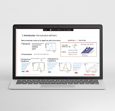
The introduction of single site catalysts and multiple reactor technology allows the design of new Polyolefin resins with improved properties for each particular application, and the Chemical Composition Distribution (CCD) has become the most discriminating microstructure parameter in these polymers. The proper analysis of the CCD necessarily requires a fractionation process, typically done according to crystallizability; existing analytical techniques like Temperature Rising Elution Fractionation TREF 1 and Crystallization Analysis Fractionation CRYSTAF 2-4 have shown in the last years to be of great value in the polyolefins industry. Although analytical time has been reduced to a few hours per sample in both CRYSTAF and TREF, a faster method without sacrificing resolution was required, which ended in the development of a new technique known as Crystallization Elution Fractionation (CEF) 5.
CEF was introduced in 2006 at the 1st International Conference on Polyolefin Characterization (ICPC) in Houston, TX 6. CEF combines the separation power of CRYSTAF in the crystallization step with the separation achieved in TREF during the elution cycle. CEF has been shown to be superior to both TREF and CRYSTAF and is capable to provide very fast analysis of the composition distribution of polyolefins for high-throughput applications 7.
Crystallization Elution Fractionation mechanism
The principles of TREF have been widely discussed 1,4 and are shown schematically in Figure 1a where three components loaded on the head of the column are deposited in situ (crystallization step) with no physical separation but acquiring the potential to be separated in the elution step as shown. In our search for new techniques to improve resolution it was our intention to combine the separation power of TREF, in the elution step, with the CRYSTAF separation mechanism, in the crystallization step, but CRYSTAF as such does not physically separate fractions it only monitors the crystallization process analyzing the cumulative crystallization curve 3. To achieve a physical separation of fractions in the crystallization step a new approach was developed that is defined as Dynamic Crystallization 5-7 which will be described below.
Dynamic Crystallization:
In Dynamic Crystallization a small flow of solvent, Fc, is passed through the column during cooling, in such a way that when a component reaches its crystallization temperature it is segregated from the moving solution and it is anchored on the support while the other components, remaining in solution, will move along the column until they reach their own crystallization temperature. At the end of the crystallization cycle the components are separated inside the column according to crystallizability as shown in Figure 1b in the crystallization step.
Once completed the cooling cycle, the flow is interrupted and the column heated for a few minutes at a temperature, Td , where all components would be dissolved meanwhile remaining in the column; if applying a solvent flow, Fd, at this step to elute the components out of the column they will be separated according to CRYSTAF mechanism. To maximize resolution power in DC, analytical conditions need to be optimized as described in previous publication 7.
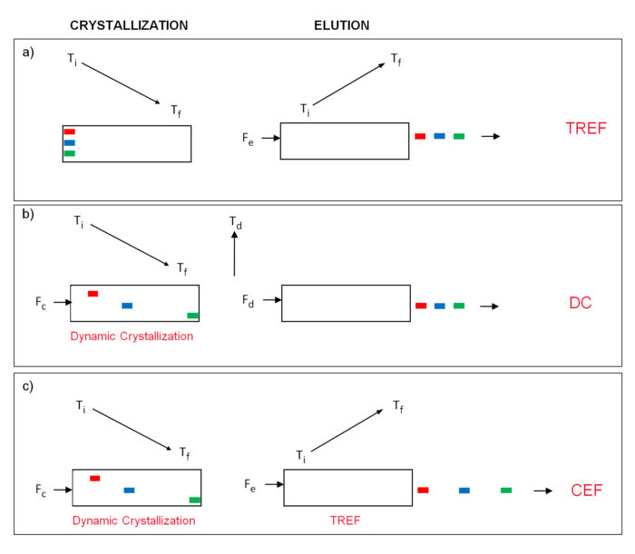
Figure 1. Principles of TREF, DC and CEF.
Crystallization Elution Fractionation:
Once developed the Dynamic Crystallization as a new separation process, it was easy to realize the possibility of combining this crystallization step with a final elution cycle, as in TREF, to obtain a new and extended separation. This is represented in Figure 1c where the Dynamic Crystallization cycle, at a crystallization flow of Fc, is followed by the temperature rising elution cycle, with a flow Fe as in TREF. The new process is known as Crystallization Elution Fractionation (CEF) because it combines the separation obtained in the crystallization step with the one obtained in the elution cycle; this is schematically represented in figure 1c by the extended separation of the three components at the exit of the column in CEF analysis as compared to the TREF approach.
Experimental
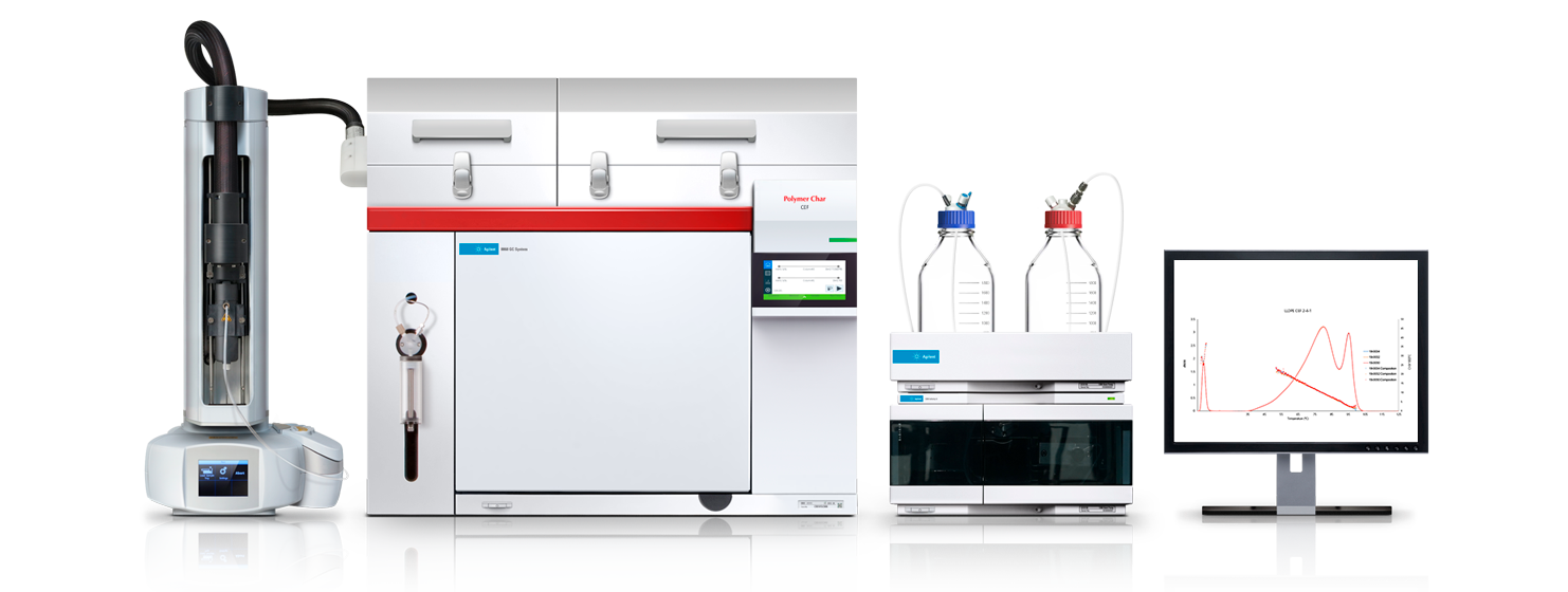
CEF, DC and TREF experiments were performed in a specially developed bench-top instrument. As the interest of CEF technology is focused not only on classical Chemical Composition Distribution measurement but also on high Throughput Analysis, the instrument was built incorporating an autosampler with capacity of 70 vials of 10 ml.
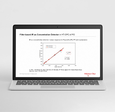
The CEF instrument diagram is quite simple as shown in Figure 2. The autosampler dissolves the sample in o-dichlorobenzene and it is loaded into the injection valve loop through the syringe dispenser. The sample is injected with the pump flow into the column head and the DC process begins at a given cooling rate and crystallization flow. As the crystallization ends, the oven starts the heating program and flow is adapted to the elution flow to obtain the CEF analysis passing through the column to a dual wavelength infrared detector, so concentration and composition can be measured at once. A dual capillary viscometer detector can be added to the system to measure the composition – molar mass dependence.
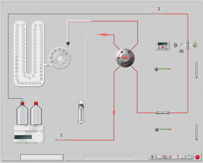
Figure 2. Schematic diagram of a Polymer Char CEF bench-top instrument.
CEF and TREF comparison
CEF and TREF analyses of a blend of two metallocene resins were performed at the same cooling rate of 2ºC/min and with a heating rate of 2ºC/min. The results are shown in Figure 3.
The extended separation between peaks in CEF over TREF (8ºC) corresponds to the extra DC separation (present in CEF only), that at a heating rate of 2ºC/min results in 4 min separation time, which at an elution flow of 1 mL/min corresponds to an extended volume separation of 4 mL indicating that the DC process deposited the fractions (colored spots in Figure 3) of the column empty volume, separated 4 mL one from the other.
Resolution in CEF is quite superior to TREF as shown by the baseline between peaks being closer to zero in CEF.
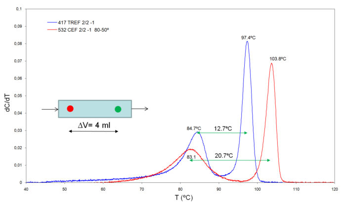
Figure 3. Comparison of CEF and TREF analysis of a blend under similar analytical conditions.
High-speed CEF analysis
The CEF analysis can be advantageous over TREF to improve resolution, as in Figure 3, or to speed up analysis for high-throughput operation achieving same resolution power but at a significant shorter time than TREF.
The use of a two heated zones autosampler, where samples are being prepared (automated vial filling and dissolution) to be injected into the CEF column, in combination with high-speed column technology, allows the analysis of samples every 25 minutes or 50 samples per day, at a crystallization rate of 5ºC/m and heating rate of 10ºC/m.
The reproducibility of the technique is extremely good as shown in Figure 4 with ten consecutive analysis of the same sample placed in different vials.
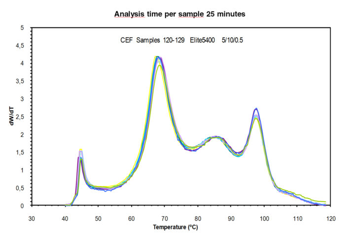
Figure 4. Analysis of 10 samples in different vials of a multi-reactor resin. Analysis time per sample 25 minutes.
Conclusions
A new approach to measure the Chemical Composition Distribution in polyolefins has been developed “Crystallization Elution Fractionation” (CEF) which is superior in resolution, speed and hardware simplicity over existing TREF and CRYSTAF techniques.
CEF is well adapted to high-throughput analysis in combinatorial chemistry tools being capable of analyzing samples with reasonable resolution in less than 30 minutes.
It is expected that CEF will replace most of TREF and CRYSTAF work in the future analysis of the CCD in Polyolefins; TREF and CRYSTAF instrumentation will be required only for the analysis of Polypropylene / Polyethylene combinations where under-cooling differences will demand it 8.
References
- L. Wild and T. Ryle, Polym. Prepr., Am. Chem. Soc., Polym. Chem. Div., 18, 182 (1977).
- B. Monrabal, J. Appl. Polym. Sci., 52, 491 (1994).
- B. Monrabal, Crystallization Analysis fractionation, US Patent 5,222,390 (1991).
- B. Monrabal, Encyclopedia of Analytical Chemistry, John Wiley & Sons, 2000, p. 8074-8094.
- B. Monrabal, Crystallization Elution Fractionation, Patent Application WO 2007/104804 A2.
- Macromolecular Symposia.Vol. 257, p. 71-79 B. Monrabal, J. Sancho-Tello, N. Mayo, L. Romero (2007).
- Macromolecular Symposia Vol.282, p. 14-24, Monrabal, L. Romero, N. Mayo, J. Sancho-Tello (2009).
- Analytical and Bioanalytical Chemistry. Separation Science of Macromolecules. Vol. 399, Number 4, p. 1557–1561. B. Monrabal, P. del Hierro (2011).